Skip to article frontmatterSkip to article content
Site not loading correctly?

This may be due to an incorrect BASE_URL configuration. See the MyST Documentation for reference.

Tutorial

Stabilizer Formalism

Abstract

The stabilizer formalism of quantum error correction.

Keywords:qubitsRepetition Codebit-flipsphase errors.

The stabilizer formalism is a method for creating error correcting codes using the Pauli-group. In addition to allowing certain errors to be detected and corrected, logical gates can also be performed in this framework.

Pauli-group

The generators of the qubit Pauli-group are

P1=X,Z,iI.\mathcal{P}_1 = \langle X, Z, i\mathbb{I} \rangle.

From these operators all elements of the one qubit Pauli-group can be generated. The Pauli-group is the set of Pauli-operators plus identity with all possible phases of {±1,±i}\{\pm 1, \pm i \}.

The nn-qubit Pauli-group , Pn\mathcal{P}_n, is then the nn-fold tensor product of elements in the one qubit Pauli-group. All elements in Pn\mathcal{P}_n either commute or anit-commute,

P1P2=(±)P2P1    P1,P2  Pn,P_1P_2 = (\pm)P_2P_1 ~~ \forall ~ ~ P_1, P_2~\in~\mathcal{P}_n,

All elements of the Pauli-group have eigenvalues {+1,1}\{+1, -1\} or {+i,i}\{+i, -i\}. Here, we mostly consider just the elements with eigenvalues {+1,1}\{+1, -1\} (the Hermitian elements of the Pauli-group).

See the Pauli Group Page for more detail.

Stabilizer Codes

Definition

The stabilizers of an error correcting code are defined as

S={PiPn:PiψL=ψL  ψL[Pi,Pj]=0  (i,j)},\mathcal{S} = \big\{ P_i \in \mathcal{P}_n: P_i \ket{\psi}_L = \ket{\psi}_L~\forall~\ket{\psi}_L \wedge [P_i, P_j] = 0 ~ \forall ~ (i,j) \big\},

such that IS-\mathbb{I} \notin \mathcal{S}. The stabilizers are therefore an Abelian subgroup of the nn-qubit Pauli-group, Pn\mathcal{P}_n, such that all logical states (states in the code space) are (+1)(+1) eigenstates of each stabilizer, that does not contain the negative identity operator.

The justification of these conditions are as follows:

  1. PiψL=ψL  ψLP_i \ket{\psi}_L = \ket{\psi}_L~\forall~\ket{\psi}_L:

    This avoids any logical information encoded in the code space being destroyed when a stablizer is measured on ψL\ket{\psi}_L.

    Further Details

    A state, ω\ket{\omega} is said to be stabilized by an operator UU if Uω=ωU\ket{\omega} = \ket{\omega}, meaning ω\ket{\omega} is a (+1)(+1) eigenstate of UU.

    From the above definition of S\mathcal{S}, it can be seen that  PiS\forall~P_i \in \mathcal{S} all logical states ψL\ket{\psi}_L are stabilized by PiP_i. Therefore, if one were to measure or apply PiP_i on any logical state ψL\ket{\psi}_L they would return the state ψL\ket{\psi}_L unchanged. This avoids any logical information encoded in the code space being destroyed when a stablizer is measured on ψL\ket{\psi}_L. (Does it also prevent loss of logical information in general? I am currently not sure).

    One can reverse this definition, and defined the code space to be the subspace of the total Hilbert space that is stabilized by all elements of S\mathcal{S}. Phrased alternatively, the code space is defined as the intersection of all (+1)(+1) eigenspaces of the elements of S\mathcal{S}.

  2. [Pi,Pj]=0[P_i, P_j] = 0:

    If this condition is not met, only the trivial space can be stabilized.

    Proof

    Let Pi,PjPnP_i, P_j \in \mathcal{P}_n such that [Pi,Pj]0[P_i, P_j] \neq 0. Moreover, assume they both stabilize ψL\ket{\psi}_L such that

    PiψL=PjψL=ψL.P_i \ket{\psi}_L = P_j \ket{\psi}_L = \ket{\psi}_L.

    Firstly, note that given that all elements of Pn\mathcal{P}_n commute or anti-commute,

    [Pi,Pj]0    PiPj+PjPi=0.[P_i, P_j] \neq 0 \implies P_iP_j + P_jP_i = 0.

    Secondly, the products, PiPjP_iP_j and PjPiP_jP_i also stabilize ψL\ket{\psi}_L if PiP_i and PjP_j individually stabilize ψL\ket{\psi}_L, such that

    PiPjψL=ψL,PjPiψL=ψL.\begin{align*} P_iP_j \ket{\psi}_L &= \ket{\psi}_L, \\ P_jP_i \ket{\psi}_L &= \ket{\psi}_L. \end{align*}

    Putting these facts together implies that

    PjPiψL=PiPjψL,=ψL,=ψL.\begin{align*} P_jP_i \ket{\psi}_L &= - P_iP_j \ket{\psi}_L, \\ &= - \ket{\psi}_L, \\ &= \ket{\psi}_L. \end{align*}

    This is only true if ψL=0\ket{\psi}_L = 0, meaning that non-Abelian subgroups of Pn\mathcal{P}_n can only stabilize a trivial subspace.

    (Note, the equation ψ=ψ\ket{\psi}=-\ket{\psi} is about the physical equivalence of vectors in a Hilbert space, with this equation only being satasfied for the zero vector. It is not about whether two states are physically distinguishable under global phases.)

  3. IS- \mathbb{I} \notin \mathcal{S}:

    If this condition is not met, only the trivial space can be stabilized.

    Proof

    All states are stabilized by I\mathbb{I},

    (I)ψL=ψL.(\mathbb{I} ) \ket{\psi}_L = \ket{\psi}_L.

    Hence, IS\mathbb{I} \in \mathcal{S} for all possible S\mathcal{S}.

    If one assumes that IS-\mathbb{I} \in \mathcal{S}, then one needs

    (I)ψL=ψL,\big( - \mathbb{I} \big) \ket{\psi}_L = \ket{\psi}_L,

    by definition of S\mathcal{S}. Combining these two facts implys that

    ψL=ψL,\ket{\psi}_L = - \ket{\psi}_L,

    which is only true if ψL=0\ket{\psi}_L = 0, meaning that S\mathcal{S} would only stabilize a trivial subspace.

The Role of the Stabilizers

The stabilizers are used to separate a Hilbert space into a series of orthogonal subspaces, as per the structure of QEC codes.

Each stabliser, PiP_i, is an element of the Pauli-group and can therefore be written as

Pi=Π+1iΠ1i,P_i = \Pi^i_{+1} - \Pi^i_{-1},

where Π+1i\Pi^i_{+1} is the projector onto the +1 eigenspace of PiP_i and Π1i\Pi^i_{-1} the projector onto the -1 eigenspace of PiP_i. One can then defined the code space via the projector

ΠCL=i=0SΠ+1i,\Pi_{\mathfrak{C}_L} = \cap_{i=0}^{\vert \mathcal{S} \vert} \Pi^i_{+1},

which is the projector onto the intersection of all the positive eigenspaces of the stabilizers.

The intersection of all the different combinations of the positive and negative eigenspaces of the stabilizers are all pairwise orthogonal, and they define each of the orthogonal subspaces of the QEC code.

An error that maps the code space to one of these orthogonal subspaces can therefore be detected by measuring the observable who’s eigenspaces are exactly these orthogonal subspaces.
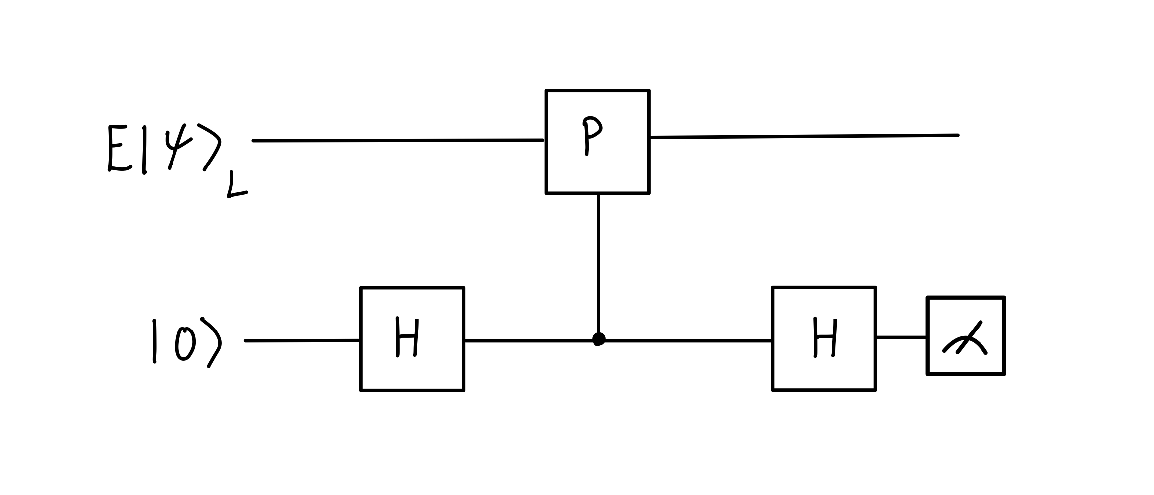
Measuring Stabilizer

All elements of Pn\mathcal{P}_n are unitary. If PPnP \in \mathcal{P}_n is also Hermitian, then any stabilizer PP can be measured on the logic state indirectly, with the measurement outcome stored in an ancilla 💭.

A schematic of the circuit used to measure the stabilizer P on the logical state \ket{\psi}_L.

A schematic of the circuit used to measure the stabilizer PP on the logical state ψL\ket{\psi}_L.

Assume that PPnP \in \mathcal{P}_n is a stabilizer of the logical state ψL\ket{\psi}_L such that PψL=ψLP \ket{\psi}_L = \ket{\psi}_L. Let EE be some correctable error that has occurred on the logical state, such that P(EψL)=EψLP ( E \ket{\psi}_L) = E \ket{\psi}_L or P(EψL)=EψLP ( E \ket{\psi}_L) = - E \ket{\psi}_L, depending on whether EψLE \ket{\psi}_L is in the positive or negative eigenspace of PP.

The input state into the circuit is EψL0AE\ket{\psi}_L \ket{0}_A, where AA labels the ancillary space and the LL subscript now doubles as a label for the space of the logical state.

The output state is then

12(ILIA+PLIA)EψL0A+12(ILIAPLIA)EψL1A.\frac{1}{2} \big( \mathbb{I}_L \otimes \mathbb{I}_A + P_L \otimes \mathbb{I}_A) E \ket{\psi}_L \ket{0}_A + \frac{1}{2} \big( \mathbb{I}_L \otimes \mathbb{I}_A - P_L \otimes \mathbb{I}_A) E \ket{\psi}_L \ket{1}_A.
Proof

The input state to the circuit is

EψL0A.E\ket{\psi}_L \otimes \ket{0}_A.

The controlled stabilizer gate can be written as

PLCA=IL00A+PL11A.P_LC_A = \mathbb{I}_L \otimes \ket{0}\bra{0}_A + P_L \otimes \ket{1}\bra{1}_A.

The output state of the circuit is then

(IH)PLCA(IH)(EψL0A)=(IH)(IL00A+PL11A)(EψL+)=12(IH)(EψL0+PEψL1)=12(EψL++PEψL).\begin{align*} &(\mathbb{I} \otimes H) P_L C_A (\mathbb{I} \otimes H) \big(E\ket{\psi}_L \otimes \ket{0}_A \big) \\ =& (\mathbb{I} \otimes H)\big(\mathbb{I}_L \otimes \ket{0}\bra{0}_A + P_L \otimes \ket{1}\bra{1}_A \big)\big(E \ket{\psi}_L \otimes \ket{+} \big) \\ =& \frac{1}{\sqrt{2}}(\mathbb{I} \otimes H) \big( E\ket{\psi}_L \otimes \ket{0} + PE\ket{\psi}_L \otimes \ket{1} \big) \\ =& \frac{1}{\sqrt{2}}\big( E\ket{\psi}_L \otimes \ket{+} + PE\ket{\psi}_L \otimes \ket{-} \big).\\ \end{align*}

Expanding +\ket{+} and \ket{-} in the computational basis and factorising completes the proof.

Therefore, if P(EψL)=EψLP ( E \ket{\psi}_L) = E \ket{\psi}_L, the second term will go to zero and the output state becomes

EψL0A,E \ket{\psi}_L \ket{0}_A,

such that if one measures ZZ on the ancilla they will get the outcome +1 (syndrome bit 0) with certainty.

If P(EψL)=EψLP ( E \ket{\psi}_L) = - E \ket{\psi}_L, the first term will go to zero and the output state becomes

EψL1A,E \ket{\psi}_L \ket{1}_A,

such that a ZZ measurement performed on the ancilla now gives the outcome -1 (syndrome bit 1) with certainty.

By performing the above circuit and measuring the ancilla one can therefore determine if the logical state is in the +1 or -1 eigenspace of the stabilizer PP.

This is an example of generalised measurement and Naimark’s dilation theorem.

Parity Measurements Circuits

When discussing the 2-bit repetition code it was noted that the measurement of the stabilizer was akin to performing a parity check on the qubits. Specifically, a logical qubit was encoded into space Span{00,11}{\rm Span}\{ \ket{00}, \ket{11}\} such that

ψL=α00+β11,  α2+β2=1.\ket{\psi}_L = \alpha \ket{00} + \beta \ket{11}, ~ ~ \vert \alpha \vert^2 + \vert \beta \vert^2=1.

It was then seen that it was possible to perform error detection on the set of errors {I,X1,X2}\{\mathbb{I}, X_1, X_2 \} by measuring the stabilizer Z1Z2Z_1 \otimes Z_2. If I\mathbb{I} occurs, the state stays in the code space and measuring the stabilizer gives the output +1 (syndrome bit 0). If either an X1X_1 or X2X_2 occurs, the state is mapped into the space Span{01,10}{\rm Span}\{ \ket{01}, \ket{10} \}, and a measurement of the stabilizer gives the output -1 (syndrome bit 1).

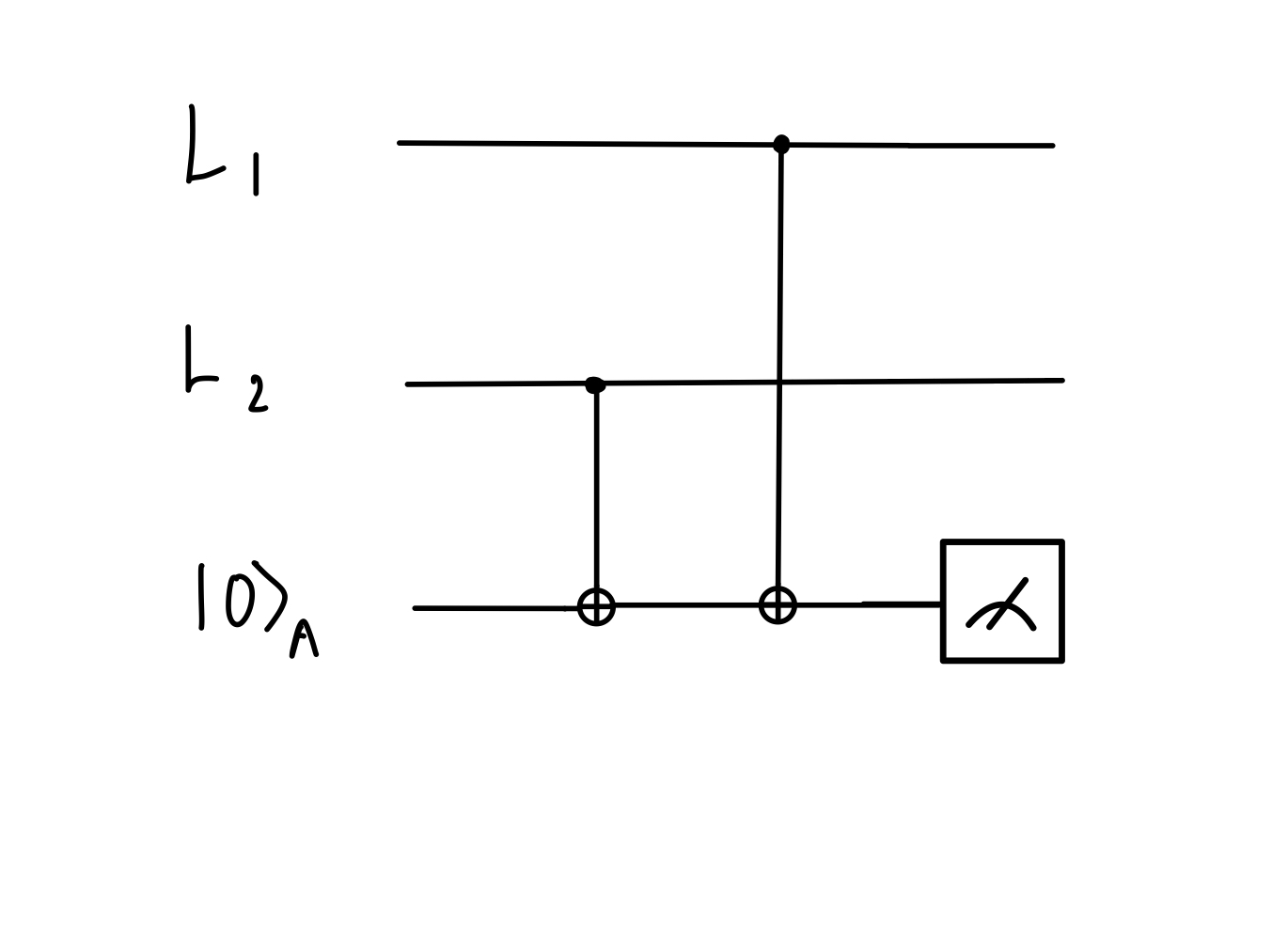
A simpler circuit can be used for measuring stabilizers that perform a parity check. The circuit for performing the parity check in the 2-bit repetition code is shown in the below figure.

A circuit that checks the parity of two qubits and stores the result in an ancilla. L_1 and L_2 are used to label the two physical qubits used to create the single logical qubit.

A circuit that checks the parity of two qubits and stores the result in an ancilla. L1L_1 and L2L_2 are used to label the two physical qubits used to create the single logical qubit.

Firstly, the parity of two bits, i1,i2{0,1}i_1, i_2 \in \{0,1\}, is given by i1i2i_1 \oplus i_2. This will be zero if both bits are zero or both bits are one. If the bits differ, it will be one.

Now, note that the action of a CNOT gate on some arbitrary computational basis state can be written as

C1X2i1i2=i1(i2i1),  i1,i2  {0,1}.C_1X_2 \ket{i_1i_2} = \ket{i_1(i_2 \oplus i_1)}, ~ ~ i_1, i_2~\in~\{0,1\}.

This works because a CNOT gate applies an XX gate to the second qubit if the first qubit is i1=1i_1 = 1. This XX gate will flip the second qubit, which can be done by adding 1 to it. Hence, if i1=0i_1 = 0 nothing is added to the second qubit and it remains i2i_2. If i1=1i_1=1 then 1 is added to i2i_2, flipping it.

From here, consider that if it is not known if an error has occurred on an arbitrary qubit encoded into the code space, Span{00,11}{\rm Span}\{\ket{00}, \ket{11}\}, the state can be written as

αi1i2+β(i11)(i21).\alpha \ket{i_1 i_2} + \beta \ket{(i_1 \oplus 1)(i_2 \oplus 1)}.

The input into the circuit is then

(αi1i2+β(i11)(i21))0A.\begin{align*} \big( \alpha \ket{i_1 i_2} + \beta \ket{(i_1 \oplus 1)(i_2 \oplus 1)} \big) \otimes \ket{0}_A. \end{align*}

The action of the first CNOT gate is then

C2XA(αi1i20A+β(i11)(i21)0A)=αi1i20i2A+β(i11)(i21)(i21)A=αi1i2i2+β(i11)(i21)(i21)A,\begin{align*} &C_2X_A \big( \alpha \ket{i_1 i_2} \otimes \ket{0}_A + \beta \ket{(i_1 \oplus 1)(i_2 \oplus 1)} \otimes \ket{0}_A \big) \\ =&\alpha \ket{i_1 i_2} \otimes \ket{0 \oplus i_2}_A + \beta \ket{(i_1 \oplus 1)(i_2 \oplus 1)} \otimes \ket{(i_2 \oplus 1)}_A \\ =& \alpha \ket{i_1 i_2} \otimes \ket{i_2} + \beta \ket{(i_1 \oplus 1)(i_2 \oplus 1)} \otimes \ket{(i_2 \oplus 1)}_A, \end{align*}

as 0i2=i20 \oplus i_2 = i_2. The action of the second CNOT gate is then

C1XA(αi1i2i2+β(i11)(i21)(i21)A)=αi1i2i2i1+β(i11)(i21)(i21)(i11)A=αi1i2i2i1+β(i11)(i21)i2i1A,\begin{align*} &C_1X_A \big( \alpha \ket{i_1 i_2} \otimes \ket{i_2} + \beta \ket{(i_1 \oplus 1)(i_2 \oplus 1)} \otimes \ket{(i_2 \oplus 1)}_A \big) \\ =&\alpha \ket{i_1 i_2} \otimes \ket{i_2 \oplus i_1} + \beta \ket{(i_1 \oplus 1)(i_2 \oplus 1)} \otimes \ket{(i_2 \oplus 1) \oplus (i_1 \oplus 1)}_A \\ =& \alpha \ket{i_1 i_2} \otimes \ket{i_2 \oplus i_1} + \beta \ket{(i_1 \oplus 1)(i_2 \oplus 1)} \otimes \ket{i_2 \oplus i_1}_A, \end{align*}

as 11=01 \oplus 1 = 0. Hence, if ZZ is measured on the computational basis then the parity is output with certainty.